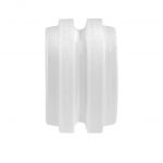
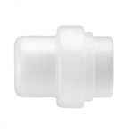
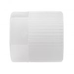
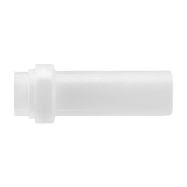
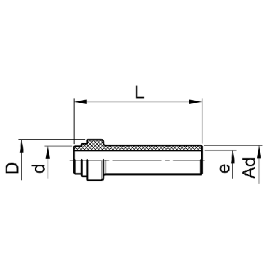
Tube stub
SO Code:
-
Art. no.: -
Technical details
Additional information
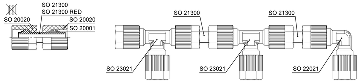
If the tube stubs are coupled with a union nut and a nut connection (union nut and compression ferrule), an adjustable union is produced.
Assembly information: Tighten the union nut on the side of the turned compression ferrule (left in pict.) with 1/4 turn. Tighten the union nut on the other side (right in pict.) 1 3/4 turns.
Recommendation: For easy and correct placement of the compression ferrule, use the assembly aid AC 870.
Assembly information: Tighten the union nut on the side of the turned compression ferrule (left in pict.) with 1/4 turn. Tighten the union nut on the other side (right in pict.) 1 3/4 turns.
Recommendation: For easy and correct placement of the compression ferrule, use the assembly aid AC 870.
With the adjustable union, parts with the same connecting thread can be connected.
+ = higher pressure on request
| Type | (Cust.) Art. no. | d | Ad | L | D | e | CAD | Legend | ||||||||||
|---|---|---|---|---|---|---|---|---|---|---|---|---|---|---|---|---|---|---|
| Type | SO 21300-6-A6 | Art. no. | 1003147 | Art. no. | d | 6.0 | Ad | 6 | L | 27.0 | D | 8.6 | e | 4.0 | CAD | Download | ||
| Type | SO 21300-8-A8 | Art. no. | 1003150 | Art. no. | d | 8.0 | Ad | 8 | L | 28.0 | D | 10.6 | e | 6.0 | CAD | Download | ||
| Type | SO 21300-10-A10 | Art. no. | 1003133 | Art. no. | d | 10.0 | Ad | 10 | L | 33.0 | D | 12.6 | e | 8.0 | CAD | Download | ||
| Type | SO 21300-12-A12 | Art. no. | 1003134 | Art. no. | d | 12.0 | Ad | 12 | L | 37.0 | D | 14.6 | e | 10.0 | CAD | Download | ||
| Type | SO 21300-12/9-A12/9 | Art. no. | 1003137 | Art. no. | • | d | 12.0 | Ad | 12 | L | 37.0 | D | 14.6 | e | 9.0 | CAD | Download | |
| Type | SO 21300-16/13-A16/13 | Art. no. | 1003132 | Art. no. | • | d | 16.0 | Ad | 16 | L | 47.5 | D | 19.7 | e | 13.0 | CAD | Download |
If the tube stubs are coupled with a union nut and a nut connection (union nut and compression ferrule), an adjustable union is produced.
Assembly information: Tighten the union nut on the side of the turned compression ferrule (left in pict.) with 1/4 turn. Tighten the union nut on the other side (right in pict.) 1 3/4 turns.
Recommendation: For easy and correct placement of the compression ferrule, use the assembly aid AC 870.
Assembly information: Tighten the union nut on the side of the turned compression ferrule (left in pict.) with 1/4 turn. Tighten the union nut on the other side (right in pict.) 1 3/4 turns.
Recommendation: For easy and correct placement of the compression ferrule, use the assembly aid AC 870.
With the adjustable union, parts with the same connecting thread can be connected.
+ = higher pressure on request