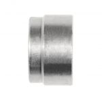
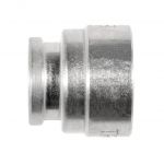
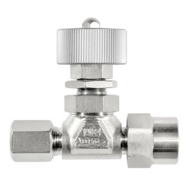
Regulierventil
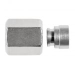
mit Übergangsmuffe SO 50030
SO Code:
-
Art.-Nr.: -
Technische Details
Ergänzende Informationen
Spezifikationen
Betriebsdruck (PN): 64 bis 100 bar
Sicherheitsfaktor: 1.5-fach
Temperatur: -40°C bis +180°C
Materialien
Ventilkomponenten: Edelstahl 1.4571 (≈ AISI 316 Ti)
Dichtungen: PTFE
Handrad: Aluminium
Betriebsdruck (PN): 64 bis 100 bar
Sicherheitsfaktor: 1.5-fach
Temperatur: -40°C bis +180°C
Materialien
Ventilkomponenten: Edelstahl 1.4571 (≈ AISI 316 Ti)
Dichtungen: PTFE
Handrad: Aluminium
Montagehinweis: Muffe ist handfest montiert. Bei Endmontage mit 1/4 Umdrehung anziehen.
Wir empfehlen eine zusätzliche Schmierung auf der Planfläche.
Wir empfehlen eine zusätzliche Schmierung auf der Planfläche.
Umrechnung für "d" bei Zollrohren:
6,35 = 1/4
9,52 = 3/8
12,7 = 1/2
6,35 = 1/4
9,52 = 3/8
12,7 = 1/2
Dokumente
-
Technische Information Sortiment Regulierventile Edelstahl Herunterladen
-
Montageanleitung Messing / Edelstahl / Aluminium / Stahl Herunterladen
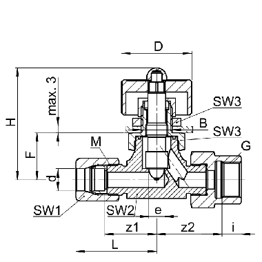
| Type | (Kd.-) Art.-Nr. | d | G | PN | H | z1 | z2 | e | kv | CAD | Legende | |||||||||||||
|---|---|---|---|---|---|---|---|---|---|---|---|---|---|---|---|---|---|---|---|---|---|---|---|---|
| Type | SO NV 51A30-4-1/8 | Art.-Nr. | 1040666 | Art.-Nr. | * | d | 4.0 | G | 1/8 | PN | 100 | H | 41.0 | z1 | 17.0 | z2 | 20.0 | e | 3.5 | kv | 2.5 | CAD | Download | |
| Type | SO NV 51A30-5-1/8 | Art.-Nr. | 1040670 | Art.-Nr. | * | d | 5.0 | G | 1/8 | PN | 100 | H | 41.0 | z1 | 17.0 | z2 | 20.0 | e | 3.5 | kv | 2.5 | CAD | Download | |
| Type | SO NV 51A30-6-1/8 | Art.-Nr. | 1040671 | Art.-Nr. | d | 6.0 | G | 1/8 | PN | 100 | H | 41.0 | z1 | 17.0 | z2 | 20.0 | e | 3.5 | kv | 2.5 | CAD | Download | ||
| Type | SO NV 51A30-6-1/4 | Art.-Nr. | 1040699 | Art.-Nr. | d | 6.0 | G | 1/4 | PN | 100 | H | 41.0 | z1 | 17.0 | z2 | 20.0 | e | 3.5 | kv | 2.5 | CAD | Download | ||
| Type | SO NV 51A30-8-1/8 | Art.-Nr. | 1040701 | Art.-Nr. | d | 8.0 | G | 1/8 | PN | 100 | H | 41.0 | z1 | 18.5 | z2 | 21.5 | e | 3.5 | kv | 3.5 | CAD | Download | ||
| Type | SO NV 51A30-8-1/4 | Art.-Nr. | 1040702 | Art.-Nr. | d | 8.0 | G | 1/4 | PN | 100 | H | 41.0 | z1 | 18.5 | z2 | 21.5 | e | 3.5 | kv | 3.5 | CAD | Download | ||
| Type | SO NV 51A30-8-3/8 | Art.-Nr. | 1040733 | Art.-Nr. | d | 8.0 | G | 3/8 | PN | 100 | H | 41.0 | z1 | 18.5 | z2 | 21.5 | e | 3.5 | kv | 3.5 | CAD | Download | ||
| Type | SO NV 51A30-10-1/4 | Art.-Nr. | 1040739 | Art.-Nr. | d | 10.0 | G | 1/4 | PN | 64 | H | 57.5 | z1 | 23.5 | z2 | 26.5 | e | 7.0 | kv | 11.0 | CAD | Download | ||
| Type | SO NV 51A30-10-3/8 | Art.-Nr. | 1040741 | Art.-Nr. | d | 10.0 | G | 3/8 | PN | 64 | H | 57.5 | z1 | 23.5 | z2 | 26.5 | e | 7.0 | kv | 11.0 | CAD | Download | ||
| Type | SO NV 51A30-12-3/8 | Art.-Nr. | 1040743 | Art.-Nr. | d | 12.0 | G | 3/8 | PN | 64 | H | 57.5 | z1 | 23.5 | z2 | 26.5 | e | 7.0 | kv | 12.0 | CAD | Download | ||
| Type | SO NV 51A30-12-1/2 | Art.-Nr. | 1040744 | Art.-Nr. | d | 12.0 | G | 1/2 | PN | 64 | H | 57.5 | z1 | 23.5 | z2 | 26.5 | e | 7.0 | kv | 12.0 | CAD | Download | ||
| Type | SO NV 51A30-15-1/2 | Art.-Nr. | 1040746 | Art.-Nr. | d | 15.0 | G | 1/2 | PN | 64 | H | 57.5 | z1 | 26.0 | z2 | 29.5 | e | 7.0 | kv | 13.0 | CAD | Download | ||
| Type | SO NV 51A30-6,35-1/8 | Art.-Nr. | 1040700 | Art.-Nr. | d | 6.35 | G | 1/8 | PN | 100 | H | 41.0 | z1 | 17.0 | z2 | 20.0 | e | 3.5 | kv | 2.5 | CAD | Download | ||
| Type | SO NV 51A30-9,52-1/4 | Art.-Nr. | 1040736 | Art.-Nr. | d | 9.52 | G | 1/4 | PN | 64 | H | 57.5 | z1 | 23.5 | z2 | 26.5 | e | 7.0 | kv | 11.0 | CAD | Download | ||
| Type | SO NV 51A30-9,52-3/8 | Art.-Nr. | 1040738 | Art.-Nr. | d | 9.52 | G | 3/8 | PN | 64 | H | 57.5 | z1 | 23.5 | z2 | 26.5 | e | 7.0 | kv | 11.0 | CAD | Download | ||
| Type | SO NV 51A30-12,7-1/2 | Art.-Nr. | 1040745 | Art.-Nr. | d | 12.7 | G | 1/2 | PN | 64 | H | 57.5 | z1 | 26.0 | z2 | 29.5 | e | 7.0 | kv | 13.0 | CAD | Download |
Spezifikationen
Betriebsdruck (PN): 64 bis 100 bar
Sicherheitsfaktor: 1.5-fach
Temperatur: -40°C bis +180°C
Materialien
Ventilkomponenten: Edelstahl 1.4571 (≈ AISI 316 Ti)
Dichtungen: PTFE
Handrad: Aluminium
Betriebsdruck (PN): 64 bis 100 bar
Sicherheitsfaktor: 1.5-fach
Temperatur: -40°C bis +180°C
Materialien
Ventilkomponenten: Edelstahl 1.4571 (≈ AISI 316 Ti)
Dichtungen: PTFE
Handrad: Aluminium
Montagehinweis: Muffe ist handfest montiert. Bei Endmontage mit 1/4 Umdrehung anziehen.
Wir empfehlen eine zusätzliche Schmierung auf der Planfläche.
Wir empfehlen eine zusätzliche Schmierung auf der Planfläche.
Umrechnung für "d" bei Zollrohren:
6,35 = 1/4
9,52 = 3/8
12,7 = 1/2
6,35 = 1/4
9,52 = 3/8
12,7 = 1/2
Dokumente
-
Technische Information Sortiment Regulierventile Edelstahl Herunterladen
-
Montageanleitung Messing / Edelstahl / Aluminium / Stahl Herunterladen