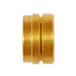
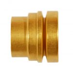
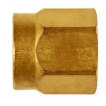
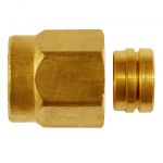
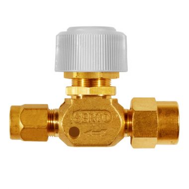
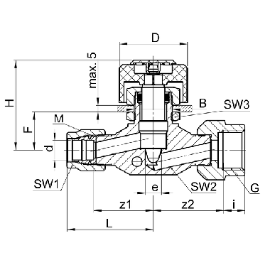
Regulierventil
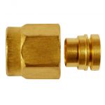
mit Übergangsmuffe SO 40030
SO Code:
-
Art.-Nr.: -
Technische Details
Ergänzende Informationen
Spezifikationen
Betriebsdruck (PN): 50 bar
Sicherheitsfaktor: 1.5-fach
Temperatur: -20°C bis +80°C
Materialien
Ventilkomponenten: Messing CW 617N
Dichtungen: NBR, PTFE, PVDF
Handrad: Polyamid
Betriebsdruck (PN): 50 bar
Sicherheitsfaktor: 1.5-fach
Temperatur: -20°C bis +80°C
Materialien
Ventilkomponenten: Messing CW 617N
Dichtungen: NBR, PTFE, PVDF
Handrad: Polyamid
Montagehinweis: Muffe ist handfest montiert. Bei Endmontage mit 1/4 Umdrehung anziehen.
Wir empfehlen eine zusätzliche Schmierung auf der Planfläche.
Wir empfehlen eine zusätzliche Schmierung auf der Planfläche.
Umrechnung für "d" bei Zollrohren:
6,35 = 1/4
9,52 = 3/8
12,7 = 1/2
6,35 = 1/4
9,52 = 3/8
12,7 = 1/2
Dokumente
-
Montageanleitung Messing / Edelstahl / Aluminium / Stahl Herunterladen
-
Technische Information Sortiment Regulierventile Messing M Herunterladen
| Type | (Kd.-) Art.-Nr. | d | G | PN | H | z1 | z2 | e | kv | CAD | Legende | |||||||||||||
|---|---|---|---|---|---|---|---|---|---|---|---|---|---|---|---|---|---|---|---|---|---|---|---|---|
| Type | SO NV 41A30-4-1/8 | Art.-Nr. | 1036574 | Art.-Nr. | * | d | 4.0 | G | 1/8 | PN | 50 | H | 47.0 | z1 | 23.0 | z2 | 26.0 | e | 3.4 | kv | 3.0 | CAD | Download | |
| Type | SO NV 41A30-5-1/8 | Art.-Nr. | 1036576 | Art.-Nr. | * | d | 5.0 | G | 1/8 | PN | 50 | H | 47.0 | z1 | 23.0 | z2 | 26.0 | e | 4.0 | kv | 3.0 | CAD | Download | |
| Type | SO NV 41A30-6-1/8 | Art.-Nr. | 1036578 | Art.-Nr. | d | 6.0 | G | 1/8 | PN | 50 | H | 47.0 | z1 | 23.0 | z2 | 26.0 | e | 4.0 | kv | 3.0 | CAD | Download | ||
| Type | SO NV 41A30-6-1/4 | Art.-Nr. | 1036579 | Art.-Nr. | d | 6.0 | G | 1/4 | PN | 50 | H | 47.0 | z1 | 23.0 | z2 | 26.0 | e | 4.0 | kv | 3.0 | CAD | Download | ||
| Type | SO NV 41A30-6-3/8 | Art.-Nr. | 1036590 | Art.-Nr. | d | 6.0 | G | 3/8 | PN | 50 | H | 47.0 | z1 | 23.0 | z2 | 26.0 | e | 4.0 | kv | 3.0 | CAD | Download | ||
| Type | SO NV 41A30-8-1/8 | Art.-Nr. | 1036573 | Art.-Nr. | d | 8.0 | G | 1/8 | PN | 50 | H | 47.0 | z1 | 23.0 | z2 | 26.0 | e | 5.0 | kv | 6.0 | CAD | Download | ||
| Type | SO NV 41A30-8-1/4 | Art.-Nr. | 1036571 | Art.-Nr. | d | 8.0 | G | 1/4 | PN | 50 | H | 47.0 | z1 | 23.0 | z2 | 27.0 | e | 5.0 | kv | 6.0 | CAD | Download | ||
| Type | SO NV 41A30-8-3/8 | Art.-Nr. | 1036544 | Art.-Nr. | d | 8.0 | G | 3/8 | PN | 50 | H | 47.0 | z1 | 23.0 | z2 | 26.0 | e | 5.0 | kv | 6.0 | CAD | Download | ||
| Type | SO NV 41A30-10-1/4 | Art.-Nr. | 1036549 | Art.-Nr. | d | 10.0 | G | 1/4 | PN | 50 | H | 54.5 | z1 | 27.0 | z2 | 30.0 | e | 6.5 | kv | 12.0 | CAD | Download | ||
| Type | SO NV 41A30-10-3/8 | Art.-Nr. | 1036550 | Art.-Nr. | d | 10.0 | G | 3/8 | PN | 50 | H | 54.5 | z1 | 27.0 | z2 | 30.0 | e | 6.5 | kv | 12.0 | CAD | Download | ||
| Type | SO NV 41A30-10-1/2 | Art.-Nr. | 1036551 | Art.-Nr. | * | d | 10.0 | G | 1/2 | PN | 50 | H | 56.5 | z1 | 31.0 | z2 | 34.0 | e | 8.0 | kv | 16.0 | CAD | Download | |
| Type | SO NV 41A30-12-1/4 | Art.-Nr. | 1036553 | Art.-Nr. | d | 12.0 | G | 1/4 | PN | 50 | H | 56.5 | z1 | 31.0 | z2 | 34.0 | e | 8.0 | kv | 16.0 | CAD | Download | ||
| Type | SO NV 41A30-12-3/8 | Art.-Nr. | 1036554 | Art.-Nr. | d | 12.0 | G | 3/8 | PN | 50 | H | 56.5 | z1 | 31.0 | z2 | 34.0 | e | 8.0 | kv | 16.0 | CAD | Download | ||
| Type | SO NV 41A30-12-1/2 | Art.-Nr. | 1036555 | Art.-Nr. | d | 12.0 | G | 3/8 | PN | 50 | H | 56.5 | z1 | 31.0 | z2 | 34.0 | e | 8.0 | kv | 16.0 | CAD | Download | ||
| Type | SO NV 41A30-14-1/2 | Art.-Nr. | 1036418 | Art.-Nr. | d | 14.0 | G | 1/2 | PN | 50 | H | 66.0 | z1 | 33.5 | z2 | 37.0 | e | 10.0 | kv | 24.5 | CAD | Download | ||
| Type | SO NV 41A30-15-1/2 | Art.-Nr. | 1036406 | Art.-Nr. | d | 15.0 | G | 1/2 | PN | 50 | H | 66.0 | z1 | 33.5 | z2 | 37.0 | e | 10.0 | kv | 24.5 | CAD | Download | ||
| Type | SO NV 41A30-6,35-1/8 | Art.-Nr. | 1036592 | Art.-Nr. | d | 6.35 | G | 1/8 | PN | 50 | H | 47.0 | z1 | 23.0 | z2 | 26.0 | e | 4.0 | kv | 3.0 | CAD | Download | ||
| Type | SO NV 41A30-9,52-1/4 | Art.-Nr. | 1036546 | Art.-Nr. | d | 9.52 | G | 1/4 | PN | 50 | H | 54.5 | z1 | 27.0 | z2 | 30.0 | e | 6.5 | kv | 12.0 | CAD | Download | ||
| Type | SO NV 41A30-9,52-3/8 | Art.-Nr. | 1036548 | Art.-Nr. | d | 9.52 | G | 3/8 | PN | 50 | H | 54.5 | z1 | 27.0 | z2 | 30.0 | e | 6.5 | kv | 12.0 | CAD | Download | ||
| Type | SO NV 41A30-12,7-3/8 | Art.-Nr. | 1036557 | Art.-Nr. | * | d | 12.7 | G | 3/8 | PN | 50 | H | 66.0 | z1 | 33.5 | z2 | 37.0 | e | 10.0 | kv | 24.5 | CAD | Download | |
| Type | SO NV 41A30-12,7-1/2 | Art.-Nr. | 1036570 | Art.-Nr. | * | d | 12.7 | G | 1/2 | PN | 50 | H | 66.0 | z1 | 33.5 | z2 | 37.0 | e | 10.0 | kv | 24.5 | CAD | Download | |
| Type | SO NV 41A30-12,7-3/4 | Art.-Nr. | 1036559 | Art.-Nr. | * | d | 12.7 | G | 3/4 | PN | 50 | H | 66.0 | z1 | 33.5 | z2 | 37.0 | e | 10.0 | kv | 24.5 | CAD | Download |
Spezifikationen
Betriebsdruck (PN): 50 bar
Sicherheitsfaktor: 1.5-fach
Temperatur: -20°C bis +80°C
Materialien
Ventilkomponenten: Messing CW 617N
Dichtungen: NBR, PTFE, PVDF
Handrad: Polyamid
Betriebsdruck (PN): 50 bar
Sicherheitsfaktor: 1.5-fach
Temperatur: -20°C bis +80°C
Materialien
Ventilkomponenten: Messing CW 617N
Dichtungen: NBR, PTFE, PVDF
Handrad: Polyamid
Montagehinweis: Muffe ist handfest montiert. Bei Endmontage mit 1/4 Umdrehung anziehen.
Wir empfehlen eine zusätzliche Schmierung auf der Planfläche.
Wir empfehlen eine zusätzliche Schmierung auf der Planfläche.
Umrechnung für "d" bei Zollrohren:
6,35 = 1/4
9,52 = 3/8
12,7 = 1/2
6,35 = 1/4
9,52 = 3/8
12,7 = 1/2
Dokumente
-
Montageanleitung Messing / Edelstahl / Aluminium / Stahl Herunterladen
-
Technische Information Sortiment Regulierventile Messing M Herunterladen